

Introduction
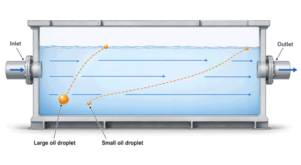
An oil-water separator does not filter oil out of water — it gives oil time and conditions to float. Every design decision inside the vessel, from inlet diffusers to coalescing packs, exists to serve one physical process: the buoyant rise of oil droplets governed by Stokes’ law.
Understanding the working principle is what separates correct specification from catalogue shopping. Two separators of identical volume can deliver effluent qualities an order of magnitude apart, depending on whether flow distribution, droplet coalescence, and outlet design are handled correctly.
For Saudi facilities — car washes, vehicle workshops, fuel stations, equipment yards, and industrial plants — the specification question is increasingly regulatory. Discharge consents reference free-oil limits, and the difference between a simple gravity chamber and a coalescing plate separator is precisely the difference between meeting 100 mg/L and meeting 10 mg/L.
This article explains both separator classes, the physics behind them, and how to match separator type to duty and discharge limit.
The Physics: Stokes’ Law and Droplet Rise Velocity
Separation performance is set by how fast an oil droplet rises, and how far it must travel before it is captured. The rise velocity of a spherical droplet in laminar conditions follows Stokes’ law:
v = g × (ρw − ρo) × d² ÷ (18 × μ)
Where: v = droplet rise velocity (m/s) g = gravitational acceleration (9.81 m/s²) ρw = water density (kg/m³) ρo = oil density (kg/m³) d = droplet diameter (m) μ = dynamic viscosity of water (Pa·s)
Three practical consequences follow directly:
- Droplet size dominates. Velocity scales with the square of diameter — a 150-micron droplet rises roughly nine times faster than a 50-micron droplet. Anything that shears oil into fine droplets (pumps, throttled valves, high-pressure washing) degrades separability before the water ever reaches the separator.
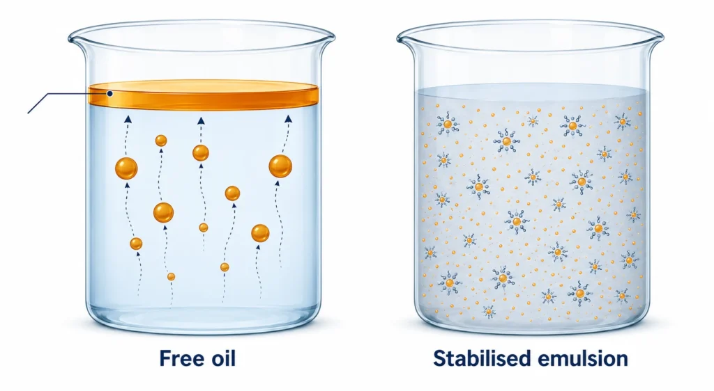
- Density difference matters. Light fuels separate faster than heavy lubricating oils. Emulsified oil with surfactants may not separate by gravity at all.
- Temperature helps. Warmer water is less viscous, so droplets rise faster — a modest advantage in Saudi ambient conditions, provided detergents have not emulsified the oil.
Key design threshold: Conventional gravity separators are typically designed to capture free-oil droplets of 150 microns and larger. Coalescing plate separators extend capture down to approximately 20–60 microns. Chemically emulsified oil (below ~20 microns with surfactant stabilisation) requires chemical treatment or dissolved air flotation — no passive separator will remove it.
Class 1: Gravity Separators
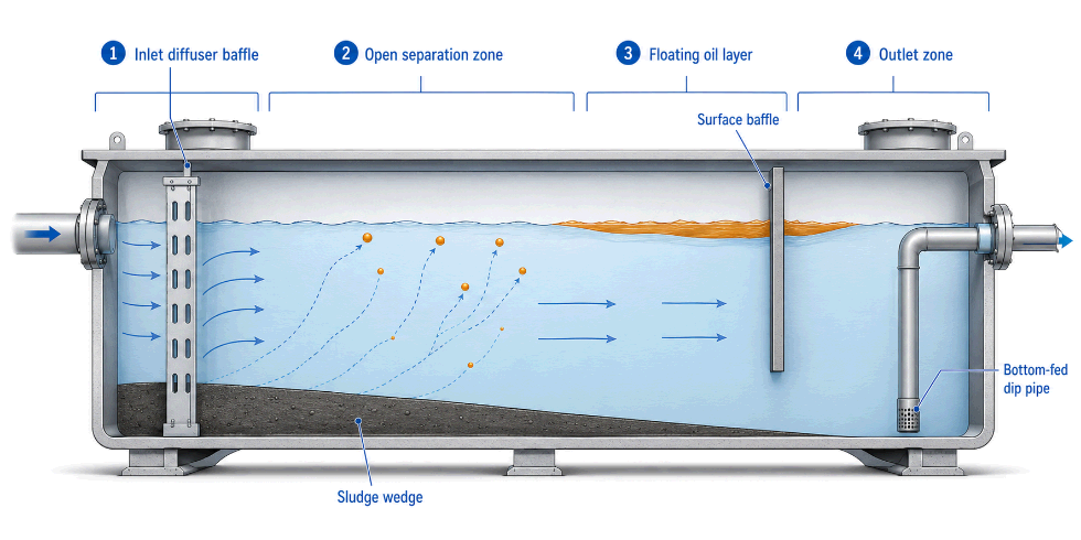
A gravity separator is a calm, elongated chamber that slows the water down until oil has time to surface. The archetype is the API separator (American Petroleum Institute design basis), a long rectangular channel proportioned so that the design droplet reaches the surface before the water reaches the outlet.
How the Gravity Separator Works — Stage by Stage
- Inlet stilling. Incoming flow passes a diffuser or baffle that kills inlet velocity and distributes flow across the chamber cross-section. Poor inlet design short-circuits the entire vessel.
- Separation zone. Water moves horizontally at low velocity (typically ≤ 15 mm/s in API-derived designs). Oil droplets rise; solids settle into the sludge zone.
- Oil accumulation. Surfaced oil collects behind an oil-retention baffle as a floating layer, periodically skimmed or pumped out.
- Outlet draw-off. Clarified water leaves through a bottom-fed dip pipe or under-baffle outlet that draws from below the oil layer.
Where Gravity Separators Fit
| Attribute | Gravity Separator |
|---|---|
| Droplet capture | ≥ 150 microns (free oil) |
| Typical effluent (free oil) | 50–100 mg/L |
| Sensitivity to flow surges | Moderate — performance degrades with velocity |
| Maintenance | Simple: skim oil, remove sludge |
| Best applications | Equipment yards, stormwater with incidental oil, primary stage ahead of a coalescer |
Class 2: Coalescing Plate Separators
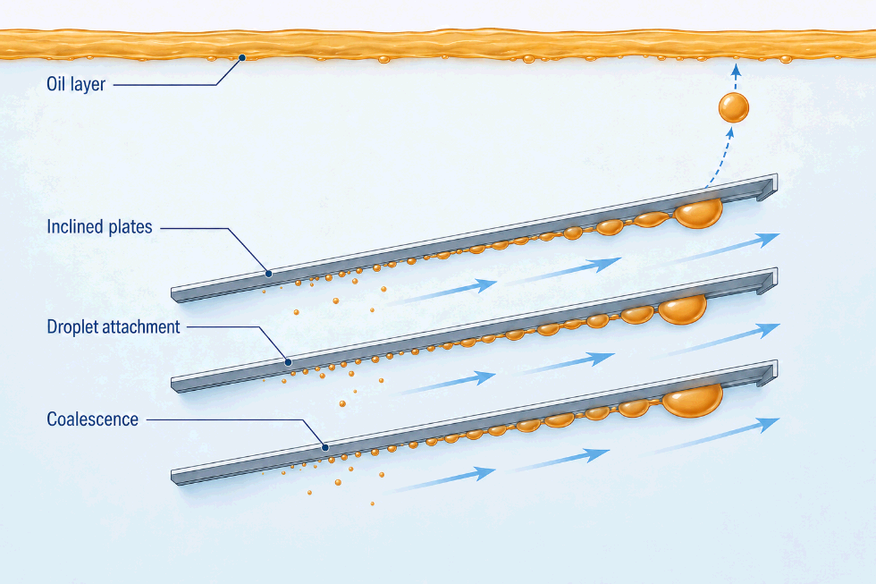
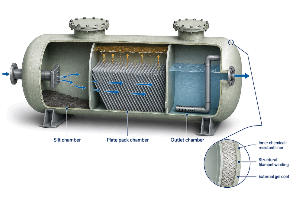
A coalescing separator shortens the distance a droplet must rise from metres to millimetres. Inside the vessel, a pack of closely spaced inclined plates (or an oleophilic media cartridge) divides the flow into thin layers. A droplet only needs to rise a few millimetres to touch the underside of a plate, where it adheres, merges with other droplets, and coalesces into larger globules that slide up the plate incline and release to the surface.
Why Plates Multiply Performance
- Reduced rise distance. Effective separation depth drops from the full water depth to the plate spacing (typically 6–20 mm).
- Coalescence. Fine droplets that could never surface on their own merge into large droplets that rise rapidly — this is how 20–60 micron capture is achieved.
- Compactness. A plate pack provides projected separation area many times the vessel footprint, so a coalescing GRP separator can be a fraction of the size of an equivalent gravity chamber.
Corrugated vs. Flat Plate Configurations
| Feature | Corrugated Plate (CPI) | Inclined Flat Plate (TPI/parallel) |
|---|---|---|
| Plate spacing | ~6–12 mm | ~12–20 mm |
| Solids tolerance | Lower — needs upstream silt trap | Higher |
| Compactness | Highest | High |
| Typical duty | Fuel stations, workshops, process water | Car washes, wash-down water with grit |
Key specification: Coalescing separators must be preceded by a silt/sediment chamber. Grit lodging in plate packs is the leading cause of channelling and performance loss. In Saudi conditions — windblown sand at fuel stations and vehicle yards — the silt chamber is not optional; size it generously.
Full-Retention vs. Bypass Separators
For surface-water and forecourt drainage, separators are further classed by how much of the design storm they treat:
| Type | Treats | Typical Use |
|---|---|---|
| Full retention | 100% of design flow through the separation stage | Fuel station forecourts, workshops, wash bays — anywhere spillage risk is continuous |
| Bypass | First flush (commonly 10% of peak flow); excess bypasses | Large car parks and paved catchments where oil arrives mainly in the first flush of rainfall |
Selection rule: if hydrocarbons are handled, dispensed, or generated on the surface being drained, specify full retention. Bypass units are for large clean catchments only.
GRP as the Separator Vessel Material
The vessel spends its life holding a stratified column of hydrocarbons, water, and anaerobic sludge — a punishing environment for steel and concrete.
- Hydrocarbon resistance. Properly specified GRP laminates with chemical-resistant resin liners tolerate continuous fuel and oil contact without the coating maintenance cycles that steel separators demand.
- Corrosion immunity. The water/oil interface and the sludge zone are aggressive corrosion sites in steel vessels; GRP has no such mechanism.
- One-piece watertightness. Buried separators must not leak hydrocarbons to soil or groundwater — a regulatory as well as environmental point. Filament-wound GRP shells eliminate the joint and crack pathways of segmented concrete units.
- Weight. A 10,000 L GRP separator can be positioned by a light crane or excavator, cutting installation cost on constrained forecourt sites.
- Verification. Every installed unit should be leak-tested before backfill and commissioning — see the FRP hydrotest guide for the procedure.
Buried installation on high water table sites requires anti-flotation anchoring, the same discipline covered for tanks in the underground vs. above-ground FRP tank guide.
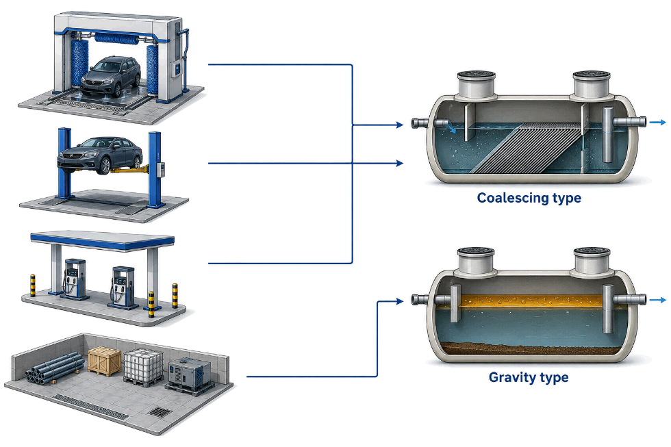
Matching Separator Type to Duty: Selection Guide
| Application | Recommended Configuration | Target Effluent (free oil) |
|---|---|---|
| Car wash / wash bay | Silt chamber + coalescing plate separator (flat plate) | ≤ 10–20 mg/L |
| Vehicle workshop / service centre | Silt chamber + full-retention coalescing separator | ≤ 10 mg/L |
| Fuel station forecourt | Full-retention coalescing separator with alarm | ≤ 5–10 mg/L |
| Equipment / plant yard runoff | Gravity separator; upgrade to coalescing if consent requires | ≤ 50–100 mg/L |
| Industrial process water | Duty-specific — gravity primary + coalescing polishing stage | Per discharge consent |
Two accessories are worth specifying by default in Saudi installations:
- Automatic closure device — a density-calibrated float that seals the outlet when the stored oil layer reaches capacity, preventing an oil discharge during an upset or major spill.
- Oil level alarm — a high-oil probe wired to a local panel, converting maintenance from calendar-based guessing to condition-based response.
What a Separator Cannot Do
Being precise about limits prevents failed installations:
- It cannot break chemical emulsions. Detergent-stabilised oil from aggressive degreasers passes straight through. Where heavy detergent use is unavoidable (some wash processes), select low-emulsifying (quick-split) detergents or plan chemical/DAF treatment.
- It cannot remove dissolved hydrocarbons. BTEX and other soluble fractions require activated carbon or biological polishing where consents demand it.
- It cannot compensate for shock flows. Pumped inflow should be avoided or buffered; if a lift station is unavoidable, place it downstream of the separator, never upstream.
- It cannot run unmaintained. A separator full of oil and silt is hydraulically a pipe — regular oil draw-off and silt removal are part of the design basis, not optional aftercare.
FAQs
1. How does an oil-water separator work? Oil is less dense than water, so oil droplets rise and form a floating layer that is retained and removed, while clarified water exits from below the surface. The rate of separation follows Stokes’ law and depends chiefly on droplet size, which is why separator designs focus on calm flow and coalescence.
2. What is the difference between a gravity and a coalescing separator? A gravity separator relies on retention time alone and captures droplets of roughly 150 microns and larger. A coalescing separator adds inclined plate packs or media that merge fine droplets, extending capture down to about 20–60 microns and achieving effluent quality around 10 mg/L free oil.
3. What effluent oil concentration can a GRP separator achieve? A well-designed coalescing unit operating within its rated flow typically achieves 5–20 mg/L free oil; simple gravity chambers achieve 50–100 mg/L. Actual performance depends on inlet droplet size distribution and maintenance condition.
4. Do I need a full-retention or bypass separator? If the drained surface handles fuel, oil, or vehicles under repair — forecourts, workshops, wash bays — specify full retention so 100% of flow is treated. Bypass units suit large paved catchments where oil arrives only in the first flush of rain.
5. Why does my separator need a silt chamber? Sand and grit blind the coalescing plate pack, causing flow channelling and oil carry-over. In Saudi Arabia’s dusty environment, an adequately sized upstream silt chamber is essential to keep the plate pack effective between services.
6. Can an oil-water separator remove emulsified oil? Not if the emulsion is chemically stabilised by detergents or surfactants. Mechanical emulsions may partially coalesce in plate packs, but stable chemical emulsions require chemical dosing, dissolved air flotation, or detergent substitution upstream.
7. Why choose GRP over steel for an oil separator? GRP is immune to the corrosion that attacks steel at the oil-water interface and in the sludge zone, requires no coating maintenance, and is light enough for simple installation. One-piece construction also removes leak paths — critical for buried units protecting soil and groundwater.
8. Should the separator be installed before or after a pump? Always before. Pumping shears oil into fine droplets that separate poorly or not at all. Where site levels force pumping, locate the lift station downstream of the separator outlet.
Conclusion
Specifying an oil-water separator correctly means matching the physics to the duty: identify the droplet sizes and flows the facility will actually generate, set the effluent target from the discharge consent, and select gravity or coalescing configuration accordingly — in a vessel material that tolerates decades of hydrocarbon and sludge contact.
For a duty-specific selection and quotation, share the following with Pioneers Fiberglass:
- Project location in Saudi Arabia
- Application (car wash, workshop, fuel station, yard runoff, process water)
- Design flow rate and drained area
- Required effluent limit or discharge consent conditions
- Buried or above-ground installation, site conditions (soil, water table), and timeline
Contact Pioneers Fiberglass for a project-specific consultation →